Anisotropic Reflections in CG
By Neil Blevins
Created On: Aug 21st 2005
Updated On: Dec 8th 2024
Software: Blender
or 3dsmax (vray)
or 3dsmax (scanline)
Before reading this tutorial, please read my Anisotropic
Reflections In The Real World
tutorial, which discusses the theory of what makes Anisotropic
Reflections in the real world.
So now how do we replicate them in 3d?
The main shader to do this is refered to as "Ward Anisotropic".
First though, it's important to know anisotropic reflections in CG can
be split up into two
categories.
- An Anisotropic
Highlight. As discussed in my
tutorial Specular
Reflections, a highlight is just an approximation of a reflection.
Some older renderers do anisotropic highlights, but not anisotropic
reflections.
- An Anisotropic Reflection takes an
actual reflection of your scene or an environment map and stretches it
based on an anisotropy direction. Most modern renderers can now do this.
Groove Direction Affects The
Direction Of Stretch
Take this real world example of a
christmas ornament that's made up of fine synthetic hairs that all
travel
in one direction.
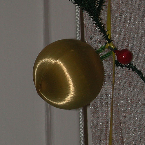
Figure 1
Here's the direction of the grooves.
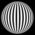
Figure 2
Here's another anisotropic highlight on a sphere...
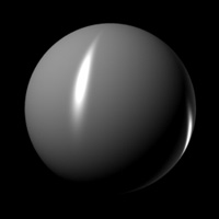
Figure 3
This is caused by grooves like this...
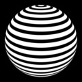
Figure 4
Here's some Anisotropic highlights on a plane. A horizontal highlight
like this...
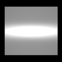
Figure 5
is caused by vertical grooves...
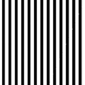
Figure 6
A vertical highlight like this...
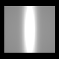
Figure 7
is caused by horizontal grooves...
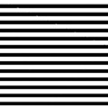
Figure 8
Here's the example of a CD or the bottom of a pot...
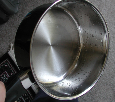
Figure 9
Here's the direction of the grooves that causes the pot picture
above.
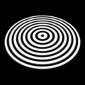
Figure 10
As you can see, the grooves always go in the perpendicular direction
to where the highlight is stretched.
Now that we have the theory, lets show how to create the effect in 3d
using a number of different 3d apps and renderers.
Blender Example
Blender's Cycles renderer does anisotropic highlights AND
reflections. You can find it in the Specular section of the Principles
BSDF:
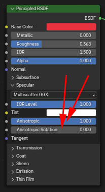
The orientation is defined in object space, so it defaults to the
grooves traveling along the y axis of the object, which of course
produces a reflection that stretches from left to right (Figure 1) (the
direction of the highlight is always perpendicular to the direction of
the grooves).
The Anisotropic Rotation goes from a value of 0 to 1, so if we want to
rotate the pattern 90 degrees, we choose a value of 0.25. And we get
the expected results (Figure 3)
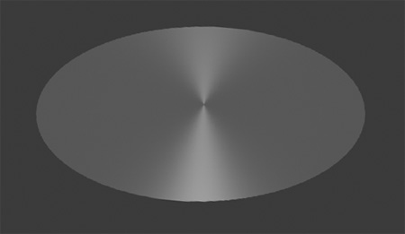
To get our pot example (Figure 9), we need the Anisotropic Rotation
value to follow a radial gradient. Unfortunately, the Gradient Texture
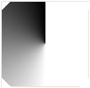
inside of Blender doesn't do the proper job, so I just used a texture created in photoshop for my gradient.

Here's my shader graph...
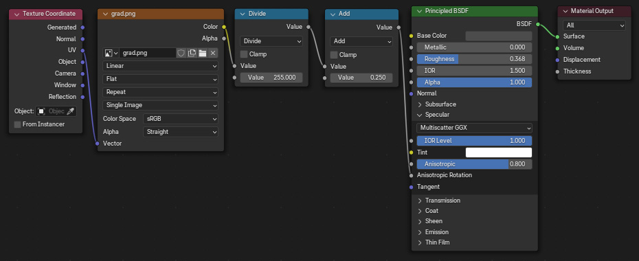
I am using the UVs of the object to assign my gradient texture. The
color value is in 0-255 space, so I divide it by 255 to get it in 0-1
space. I then add a value of 0.25 to the result so I get the grooves
pointing in the correct direction. Then I hook that into the
anisotropic Rotation value.
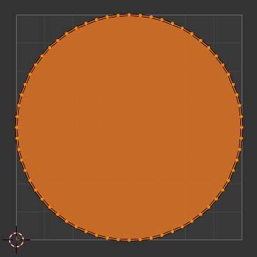
I then apply a planar UV set from the top of my object (in this case,
I'm using a flat circle). To do this, go to UV Editing mode, in the
right window change your view to the top orthographic view, go to face
select mode, choose Select -> All to select all faces, then choose
UV -> Project From View (Bounds). Your UVs will look like this.
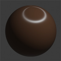
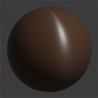
Then
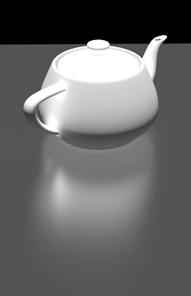
apply the material to the object, and we get the result we're after...
Here's the blend file that made the image above: blender_aniso.zip
3dsmax (vray) Example
Vray does anisotropic highlights AND
reflections.
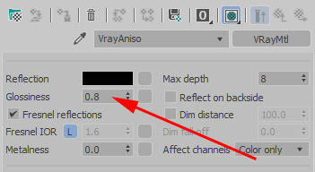
- First switch to the Vray renderer
- Create a VrayMtl
material
- Reduce Refl glossiness to a value below 1, the smaller the number
the more blurry the reflection
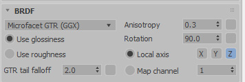
- Set Anisotropy to a number between -0.99 and 0.99, the further
the number is from 0, the more stretched the reflection. Never set it
to a value of 1 or -1, as this breaks the material and you'll get no
stretching at all
- Set rotation to the direction you want the grooves. Again, the
direction of the highlight is always perpendicular to the direction of
the grooves.
- Set Map Channel to 1 so it uses the UVs on your object for the
rotation direction
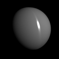
Here's the shader on a sphere, anisotropy 0.7 and Rotation 0.0 (Figure
1)
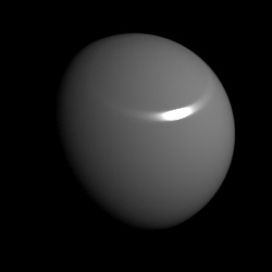
Here's the shader on a sphere, anisotropy 0.7 and Rotation 90.0 (Figure
3)
Here's an example of full anisotropic reflections on a ground plane
(Figure
7):
Here's the max file that made the image above: vray_aniso_ref.zip
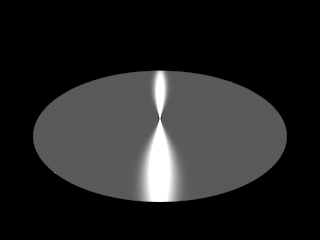
To get our pot example (Figure 9), in the Rotation map slot place a
gradient
set like this...

Note the output amount is 1.0, and the Gradient Type is
Spiral. That produces this map...
Make sure to apply a UVWMapping
modifier on your object, and set it
to planar. Then
apply the material, and we get the result we're after...
Here's the max file that made the image above: vray_aniso.zip
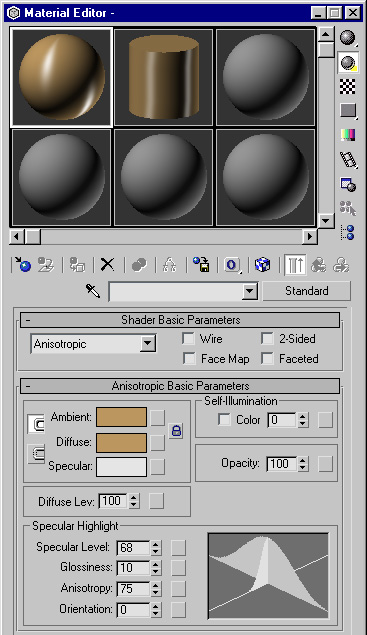
3dsmax (scanline) Example
The scanline renderer in 3dsmax only does specular
highlights, no anisotropic reflections. It is similar to a ward
anisotropic specular shader
additively
composited on top of a lambertian diffuse shader.
- switch to scanline renderer
- create a Legacy Standard material
- set to "Anisotropic"
- The default values give you something very similar to Figure 3.
The orientation is defined in object space, so it defaults to the
grooves traveling along the x axis of the object, which of course
produces a highlight that goes straight up and down (again, the
direction of the highlight is always perpendicular to the direction of
the grooves). Changing
the orientation parameter from 0 to 90 will change the direction of
your
non-existent
bumps, and hence change the look of the highlight to something similar
to Figure 1.
To achieve the pot example (Figure 9), you need to provide the
shader with a more complex direction. That's where the orientation map
slot comes in handy, which bases the orientation of the anisotropy off
of a black
and white map.
In the orientation map slot, place a Gradient Ramp map and set it up
like
this...
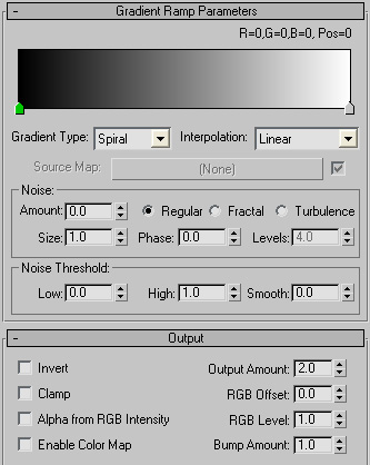
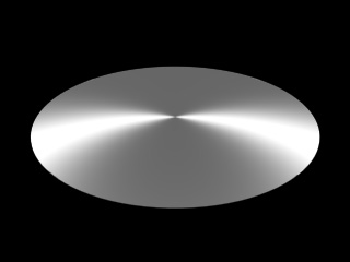
Note the output amount is set to 2.0, and the Gradient Type is
Spiral. That produces this map...
Make sure to apply a UVWMapping modifier on your object, and set it
to planar. Then
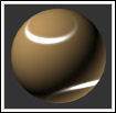
apply the material, and we get the result we're after...
Here's the max file that made the image above: max_aniso.zip
Max's Smoothing Groups Can Mess Up
Anisotropic Reflections
One thing to note, in 3dsmax (for pretty much all renderers)
smoothing groups can mess up the way your anisotropic shader produces
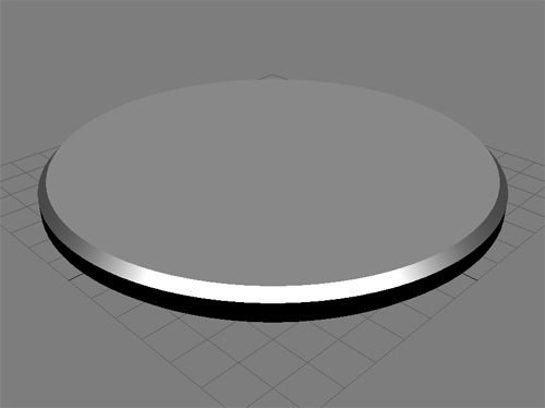
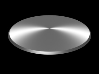
results. Here's an example. This is a chamfered cylinder with a max
standard Anisotropic shader applied to it. The edges of the cylinder
are chamfered, however, there is no smoothing between the chamfered
edge at the top of the cylinder...
And here's it rendered...
Looks good. But now lets apply a Smooth Modifier to the object, and
set it to a large angle such as 60 degrees...
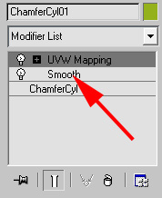
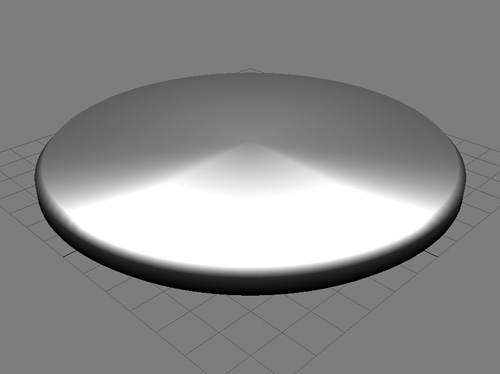
Here's the result in the max viewport, see how the chamfered edge is
now smoothing with the top face of the cylinder...
And here's the render, which looks nothing like you'd expect...
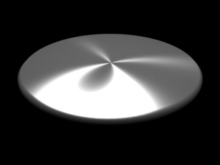
So if you're seeing odd artifacts, such as extra radial reflections,
check the smoothing on your object, it may be responsible for the error.
<>Here's a max file to check out the smoothing issue: smoothing_affects_anisotropy.zip
This site is ©2026 by Neil Blevins, All rights
are reserved.
To see hundreds of other tutorials similar to this one, visit the
Neil Blevins Education Site